General measurement system diagram
Purpose
Our purpose to analyse every measurement according to the scheme, dividing it into separate blocks, understanding the signals that pass from one to another and what are the possible errors and uncertainty effects at each block
from IPython.display import Image
Image('../img/generalized_measurement_system.png')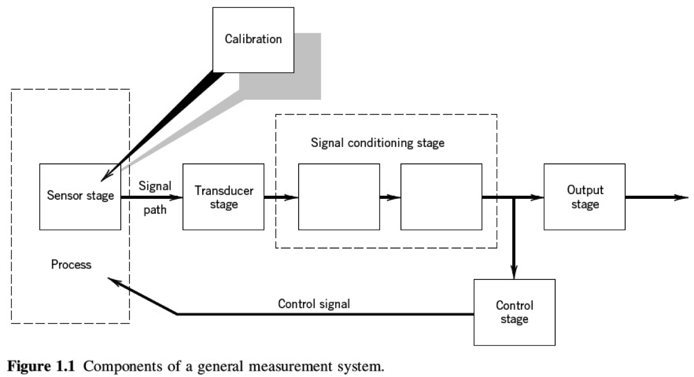
Example of measurement system diagram
Image('./fig/pressure_gage.png')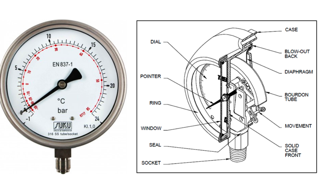
A general measurement system is a collection of components that work together to quantify a physical variable. The pressure gauge shown is a classic mechanical instrument that perfectly illustrates this system.
The Structure of a Generalized Measurement System
Based on the provided diagram, a generalized measurement system consists of the following stages:
Process: This refers to the physical system or variable that is being measured.
Sensor Stage: This is the first element that comes into contact with the quantity being measured and responds to it.
Transducer Stage: This stage converts the output from the sensor into a more usable form of energy. Often, the sensor and transducer are part of the same component.
Signal Conditioning Stage: This stage takes the transducer’s output and modifies it. This can involve amplifying the signal to make it stronger, filtering out noise, or changing its form.
Output Stage: This is where the final measurement is presented in a human-readable format, such as a pointer on a dial or a digital display.
Control Stage: In some systems, the measurement output is used to control the process itself, creating a feedback loop.
Calibration: This is not a physical component but a crucial process. It involves comparing the measurement system’s output to a known standard and making adjustments to ensure accuracy.
The Pressure Gauge as a Measurement System
The Bourdon tube pressure gauge is a mechanical device used to measure the pressure of a gas or liquid. Its components can be mapped to the stages of a generalized measurement system as follows:
| Component | Image Description | Function in the Gauge | Corresponding Measurement Stage |
|---|---|---|---|
| Socket | The threaded fitting at the bottom of the gauge. | This is the inlet that connects the gauge to the system (e.g., a pipe or tank) where the pressure is being measured. | Interface to the Process |
| Bourdon Tube | A C-shaped, hollow metal tube, typically made of bronze or stainless steel. | When fluid from the process enters the tube, the pressure causes the C-shape to straighten slightly. This movement is proportional to the applied pressure. | Sensor Stage and Transducer Stage |
| Movement | A system of levers, gears (sector gear and pinion gear), and a hairspring connected to the end of the Bourdon tube. | It takes the very small movement from the straightening Bourdon tube and mechanically amplifies it, converting it into a larger rotational movement. | Signal Conditioning Stage |
| Pointer | The needle that moves across the dial. | It is attached to the gearing of the movement. As the movement rotates, the pointer sweeps across the dial to indicate the pressure. | Part of the Output Stage |
| Dial | The face of the gauge with a calibrated scale printed on it. The units can be in bar, psi (pounds per square inch), or other pressure units. | It provides the reference scale against which the pointer’s position is read to determine the pressure value. | Part of the Output Stage |
| Case & Window | The protective housing and the clear front covering. | These components enclose and protect the delicate internal mechanism from the environment. The “blow-out back” is a safety feature designed to release internal pressure away from the operator in case of a Bourdon tube rupture. | N/A (Structural Components) |
How the Pressure Gauge Fits the Model:
Process: The pressure of the fluid inside the equipment to which the gauge is attached.
Sensor/Transducer Stage: The Bourdon Tube is the primary sensing element. It senses the pressure and acts as a transducer by converting that pressure into a small mechanical displacement at its free end.
Signal Conditioning Stage: The Movement (gears and linkages) conditions this signal. It doesn’t use electricity, but it mechanically amplifies the small tip movement of the Bourdon tube into a significant, easy-to-read rotation for the pointer.
Output Stage: The Pointer and Dial together form the output stage. They present the amplified mechanical motion as a clear, numerical pressure reading for an observer.
Control Stage: This specific pressure gauge is a purely indicative instrument and does not have a control stage. It only displays the pressure.
The Structure of a Generalized Measurement System (Second Diagram)
This diagram outlines a more detailed sequence for a measurement system:
Physical quantity to be measured: The actual parameter in the environment that we want to quantify (e.g., pressure, temperature, length).
Primary Sensing Element: This element is the first to interact with the physical quantity and produces an output that is a function of that quantity.
Variable Conversion Element: This stage, often integrated with the primary sensor, converts the signal from the sensor into a more usable form (e.g., from pressure to a small displacement).
Variable Manipulation Element: This element modifies the signal from the conversion stage, often by amplifying it to make it larger and easier to read.
Data Transmission Element: In more complex systems, this would transmit the signal from one location to another (e.g., from a sensor in a factory to a control room). In a simple mechanical device like this gauge, this “transmission” is the direct mechanical linkage.
Data Processing Element: This stage processes the transmitted signal. In digital systems, this would be a microprocessor. In this simple gauge, this stage is effectively combined with the manipulation and presentation stages.
Data Presentation Element: This is the final stage that displays the measured value in a human-readable format.
Observer: The person reading and interpreting the measurement.
The Pressure Gauge According to this Measurement System
Here is how the components of the Bourdon pressure gauge fit into this specific block diagram:
| Component | Image Description | Function in the Gauge | Corresponding Measurement Stage |
|---|---|---|---|
| Fluid Pressure | The pressure inside the pipe or vessel connected to the gauge. | This is the variable that the entire system is designed to measure. | Physical quantity to be measured |
| Bourdon Tube | The C-shaped, sealed tube that is exposed to the process pressure via the socket. | It directly senses the pressure. As pressure increases, the tube flexes and attempts to straighten. | Primary Sensing Element |
| Bourdon Tube | The same component also performs this function. | It converts the sensed pressure (a force per unit area) into a small mechanical displacement at the free end of the tube. | Variable Conversion Element |
| Movement | The system of gears (specifically the sector and pinion) and levers linked to the end of the Bourdon tube. | This mechanism takes the small linear/arc movement of the Bourdon tube’s tip and manipulates it by amplifying it into a much larger rotational movement. | Variable Manipulation Element |
| Linkages within the Movement | The physical connections between the Bourdon tube, the sector gear, the pinion gear, and the pointer. | These linkages transmit the amplified motion from the manipulation stage (gears) to the presentation stage (pointer). | Data Transmission Element |
| Pointer and Dial Assembly | The pointer moving over a pre-calibrated, numbered scale. | This combination “processes” the amplified mechanical motion by translating the angle of rotation into a specific numerical value on the scale, which represents the pressure. | Data Processing Element |
| Pointer and Dial | The visible needle and the face of the gauge with its printed scale. | These elements work together to present the final measured value in a format that can be easily read and understood by a person. | Data Presentation Element |
| Human User | The person looking at the gauge. | The observer reads the value indicated by the pointer on the dial to understand the pressure in the system. | Observer |
In summary, for the mechanical pressure gauge, the process flows as follows:
The Bourdon tube both senses the pressure and converts it to a small movement.
The internal Movement (gears) manipulates this small movement, amplifying it.
The linkages transmit this amplified motion to the pointer.
The Pointer and Dial assembly processes this motion into a number and presents it visually.
Finally, the Observer reads the result.